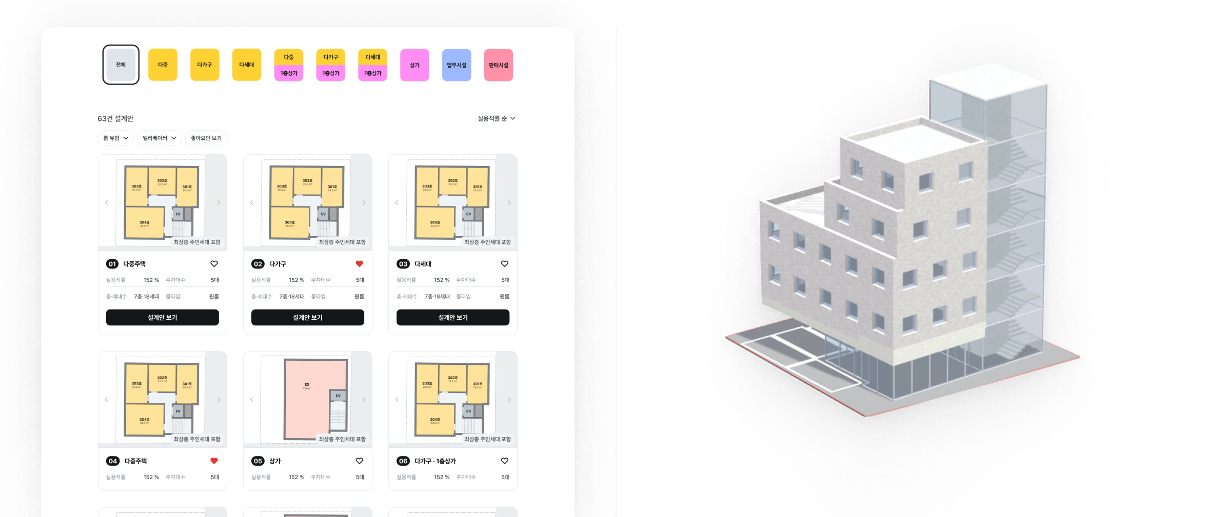
Landbook is a service that supports all the steps of new construction development for small and medium-sized land investors. Landbook's AI architect service provides building owners with various architectural design proposals by considering different plot sizes, zoning areas, and building regulations for each region. Landbook's AI architect service This project is to develop a pipeline that renders the final result of the Landbook AI architect service by using a generative image model such as diffusers. By taking 3D modeling data as input and generating realistic images that closely resemble actual buildings, it allows building owners to visualize and review what their design proposals would look like when actually constructed. Unlike conventional 3D rendering, this aims to provide high-quality visualization that considers both the texture of actual buildings and their harmony with the surrounding environment by utilizing AI-based generative models.
Pipeline Overview
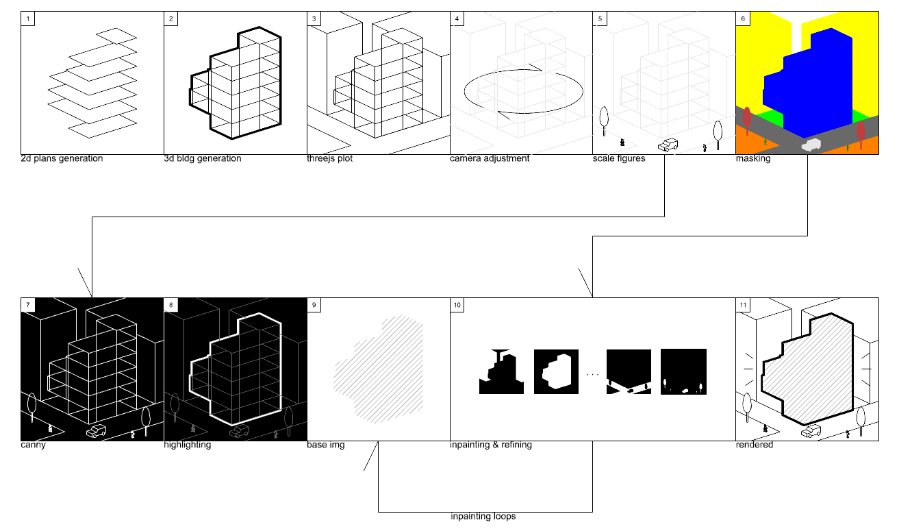
The comprehensive pipeline below ensures that the final output not only accurately represents the architectural design but also provides a realistic visualization that helps building owners better understand how the building will look in reality. The pipeline consists of the following steps:
2D Plans Generation: The process begins with generating 2D floor plans that serve as the foundation for the building design.
3D Building Generation: The 2D plans are transformed into a 3D building model with proper dimensions and structure.
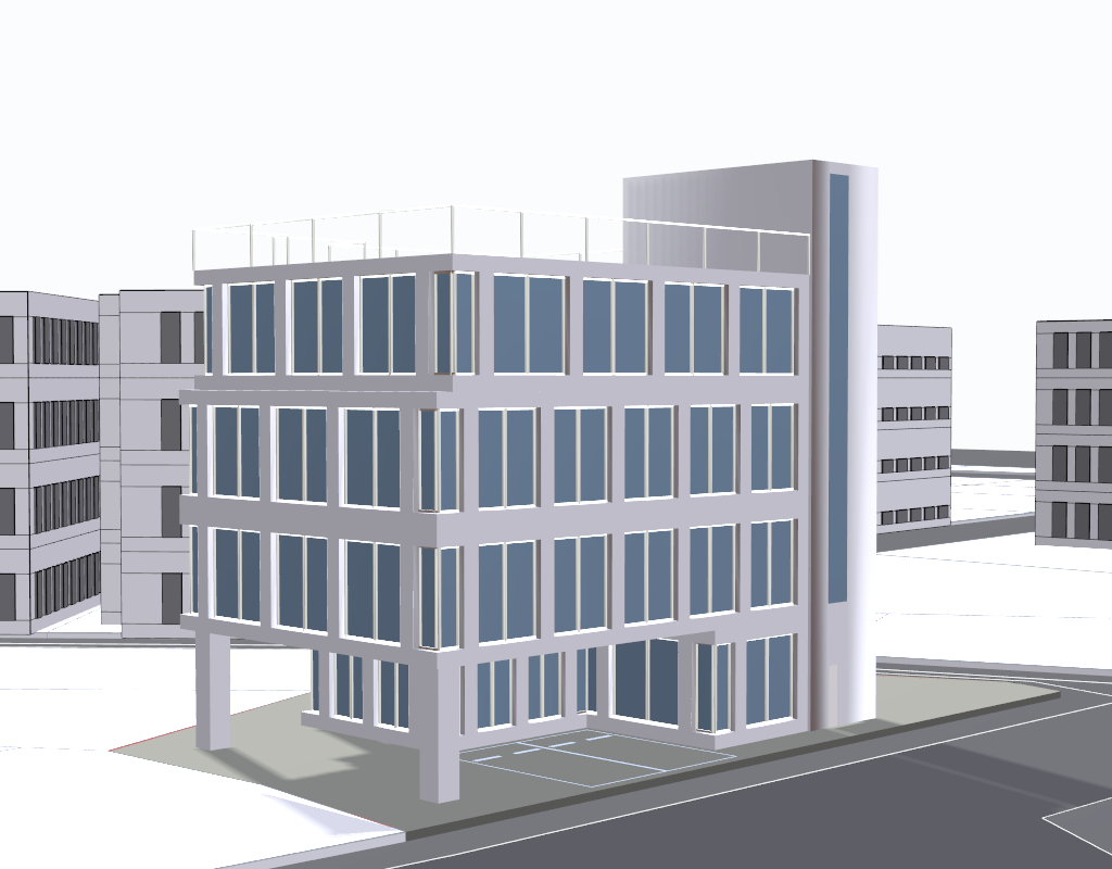
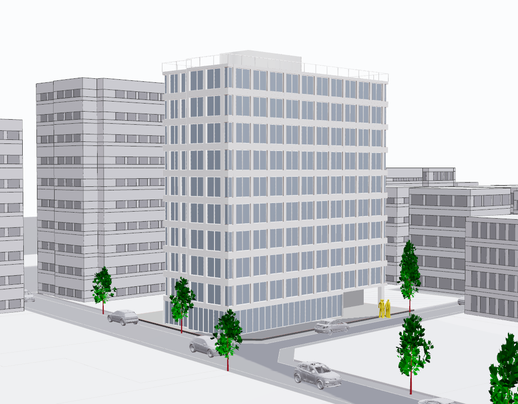
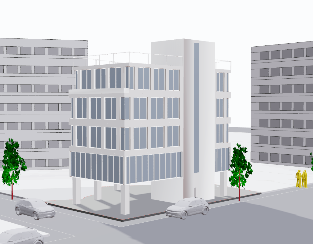
Three.js Plot: The 3D model is plotted in Three.js, allowing for visualization and manipulation.
Camera Adjustment: The viewing angle and camera position are carefully adjusted to capture the building from the most appropriate perspective.
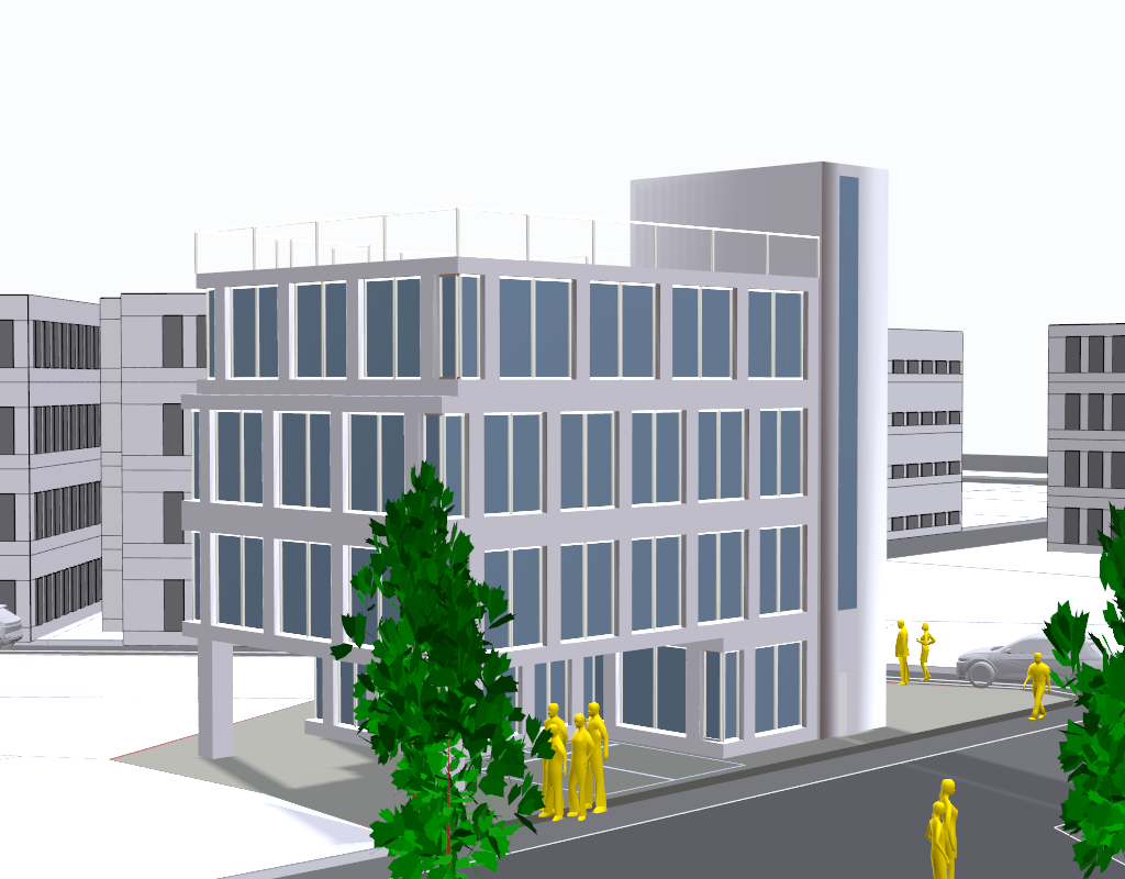
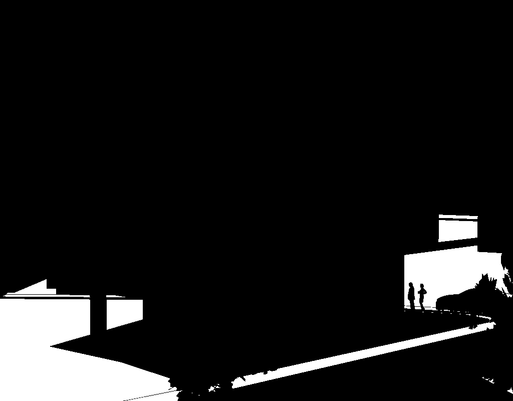
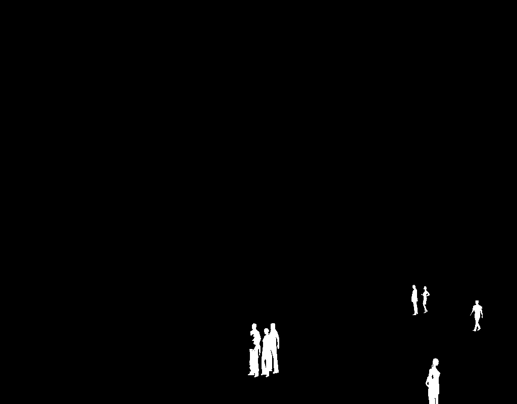
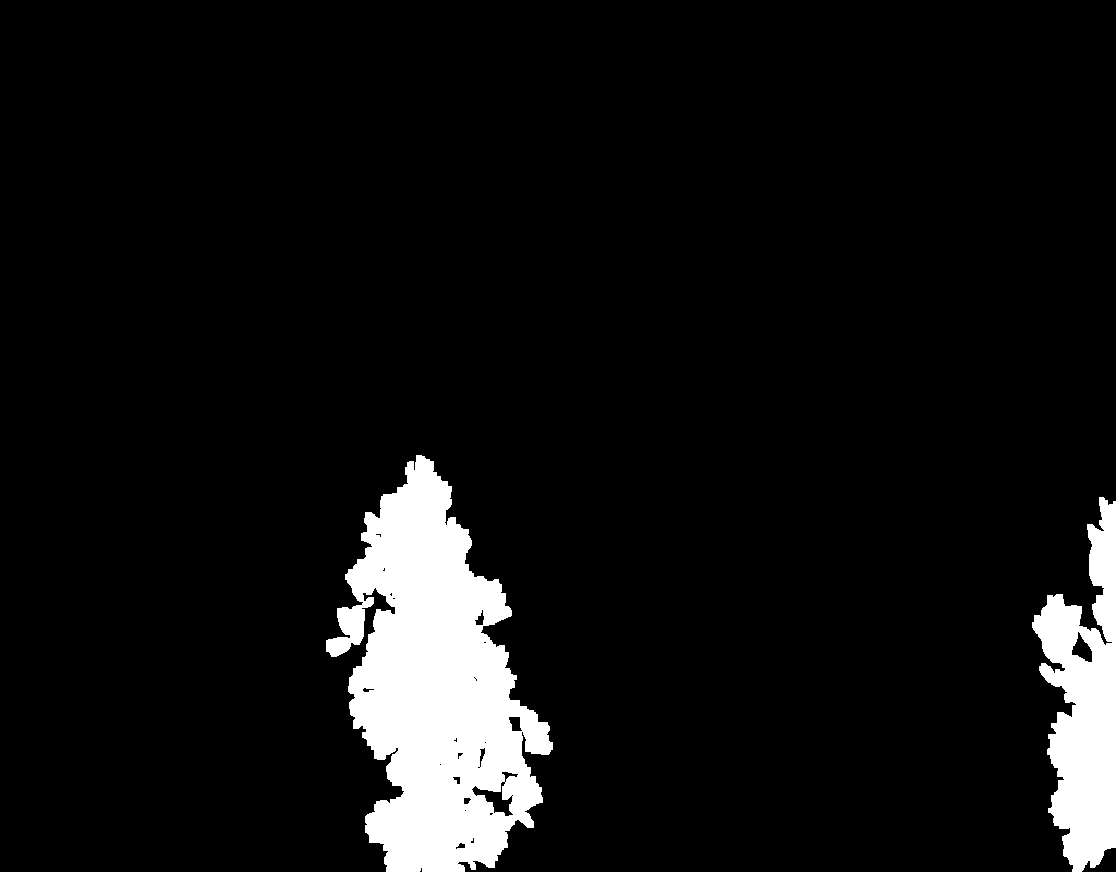
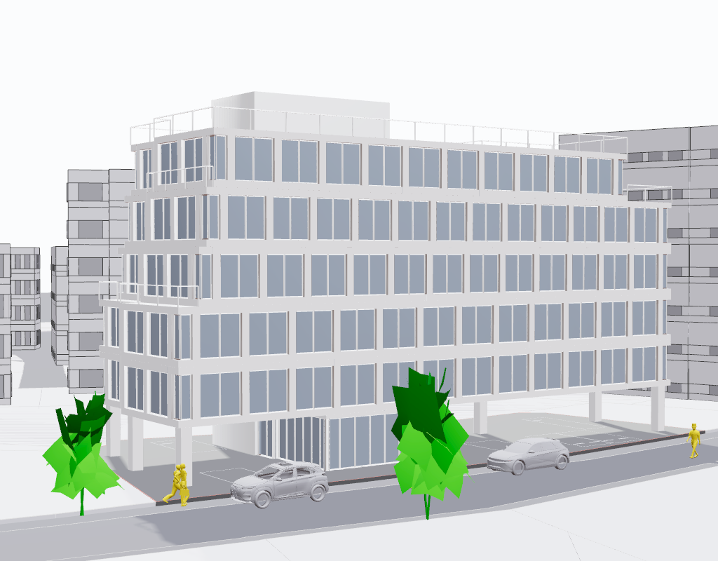
Scale Figures: Human figures, trees, and vehicles are added to provide scale reference and context to the scene.
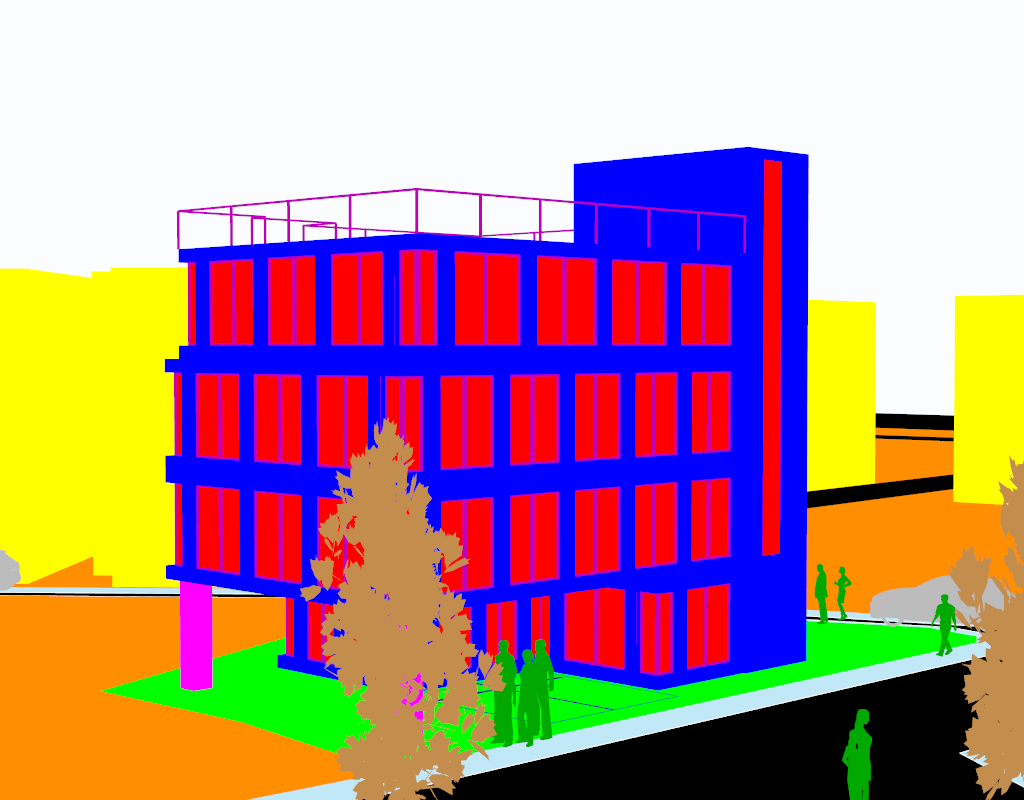
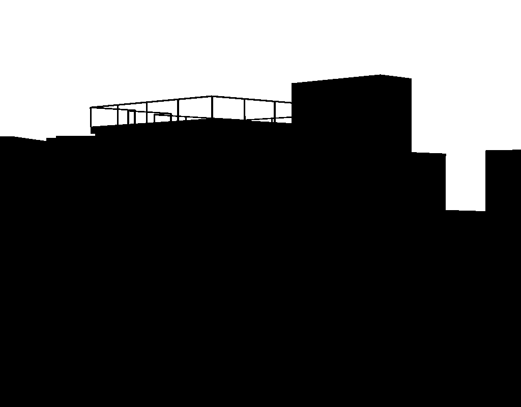
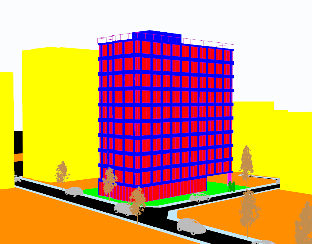
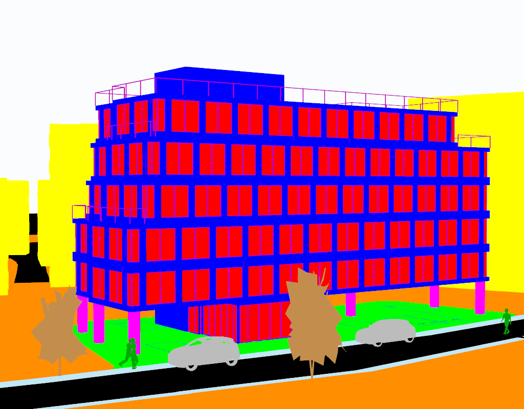
Masking: Different parts of the building and environment are masked with distinct colors to define materials and surfaces.
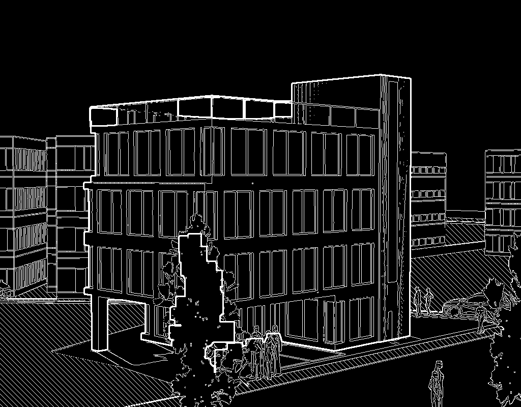
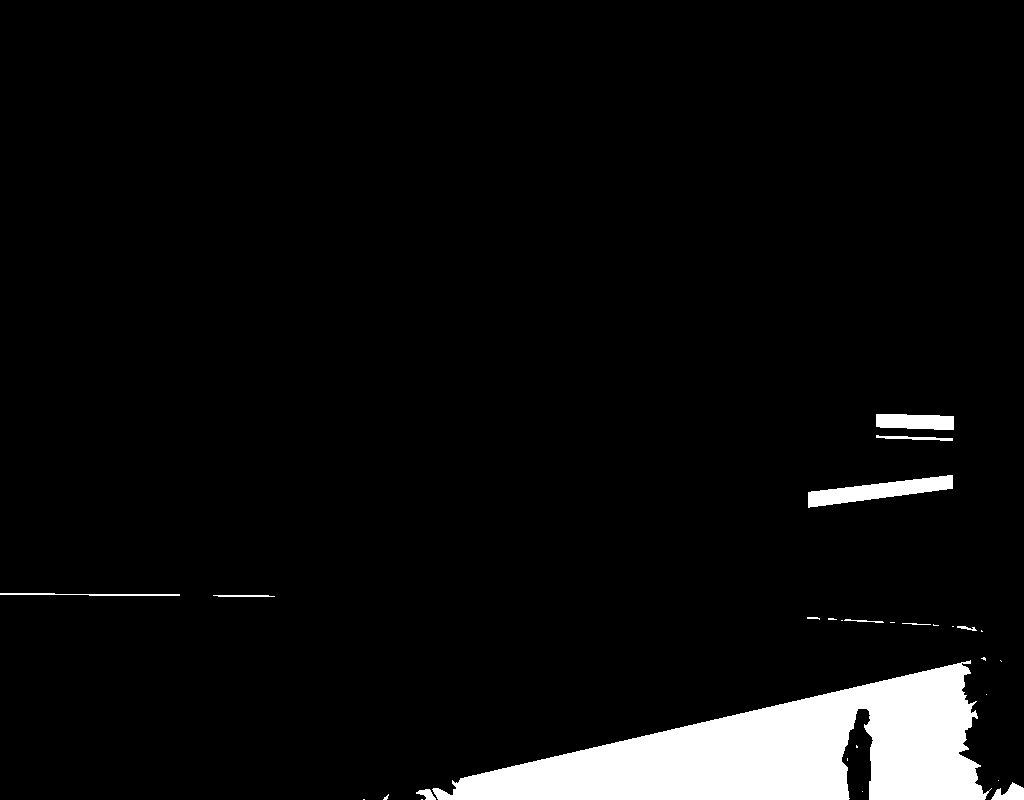
Canny Edge Detection: Edge detection is applied to create clear building outlines and details.
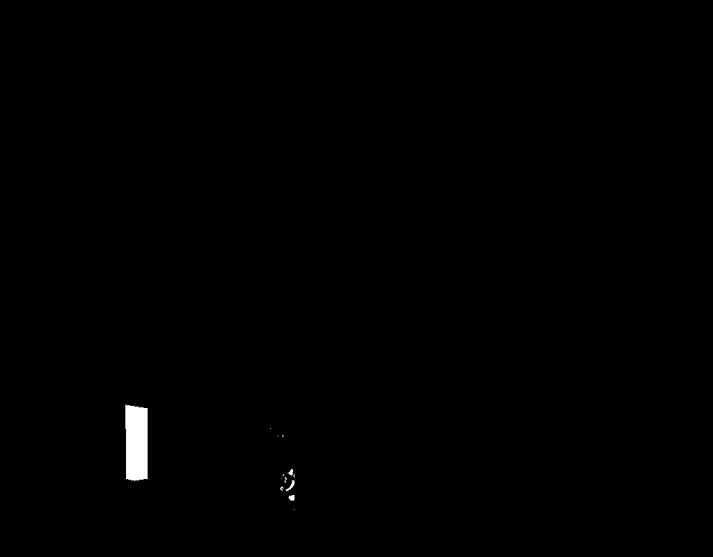
Highlighting: Important architectural features and edges are emphasized through highlighting and hatching.
Base Image Generation: A base image with proper shading and basic textures is created.
Inpainting & Refining: Multiple iterations of inpainting and refinement are performed to add realistic textures and details.
Pipeline Diagram
Camera Position Estimation
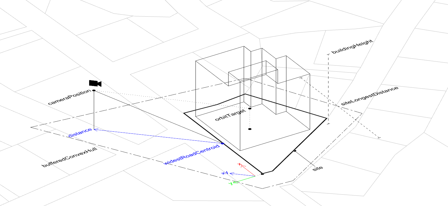
The camera position estimation is a crucial step in capturing the building from the most effective viewpoint. The algorithm determines the camera position appropriately by considering the building's dimensions, plot layout, and road positions.
Road-Based Positioning
Identifies the widest road adjacent to the building plot
Uses the road's centroid as a reference point for camera placement
Ensures the building is viewed from a natural street-level perspective
Vector Calculation
Creates a horizontal vector aligned with the widest road (X vector)
Creates a vertical vector by rotating the horizontal vector 90 degrees (Y vector)
These vectors form the basis for determining the camera's viewing direction
Height Determination and Distance Calculation
Calculates optimal camera height using two criteria
Selects the maximum value between these criteria to ensure proper building coverage
Uses trigonometry to compute the ideal distance between camera and building as follows. \[ \tan(\theta) = \frac{h}{d}, \quad d = \frac{h}{\tan(\theta)} \] where \(d\) is the distance between camera and widestRoadCentroid, \(h\) is the height of the camera, and \(\theta = \frac{\text{fov}}{2} \times \frac{\pi}{180}\)
Camera Position Estimation Diagram
    const estimateCameraPosition = (
      data: BuildingStateInfo,
      buildingHeightEstimated: number,
      fov: number,
    ) => {

      const parcelPolygon = data.plotOutline

      // Obtain the widest road object.
      // The widest road object is computed by widthRaw + edgeLength
      let widestWidth = -Infinity;
      let widestRoad = undefined;
      data.roadWidths.forEach((road) => {
        if (widestWidth < road["widthRaw"] + road["edge"].getLength()) {
          widestWidth = road["widthRaw"]
          widestRoad = road
        }
      })

      // Get the centroid of the widest road
      const widestRoadCentroid = Util.centroid(widestRoad["edge"])

      // Get the coordinates of the widest road edge
      const widestRoadEdgeCooridntaes = widestRoad["edge"]._points._coordinates

      // X vector from the widest road edge direction
      const widestRoadEdgeHVector = {
        x: widestRoadEdgeCooridntaes[0].x - widestRoadCentroid.x,
        y: widestRoadEdgeCooridntaes[0].y - widestRoadCentroid.y,
      }

      // Compute the norm of the widest road edge vector
      const widestRoadEdgeHVectorNorm = Math.sqrt(widestRoadEdgeHVector.x ** 2 + widestRoadEdgeHVector.y ** 2)

      // Normalize X vector
      const widestRoadEdgeHVectorUnit = {
        x: widestRoadEdgeHVector.x / widestRoadEdgeHVectorNorm,
        y: widestRoadEdgeHVector.y / widestRoadEdgeHVectorNorm,
      }

      // Create Y vector by rotating the X vector 90 degrees
      const radian = 90 * Math.PI / 180;
      const widestRoadEdgeVVectorUnit = {
        x: widestRoadEdgeHVectorUnit.x * Math.cos(radian) - widestRoadEdgeHVectorUnit.y * Math.sin(radian),
        y: widestRoadEdgeHVectorUnit.x * Math.sin(radian) + widestRoadEdgeHVectorUnit.y * Math.cos(radian)
      }

      // Define height criteria
      const parcelLongestDistance = calculateLongestDistance(parcelPolygon)
      const heightCriterion1 = buildingHeightEstimated / 2
      let heightCriterion2 = parcelLongestDistance / 3


      (...)


      // Determine the camera height based on the height criteria
      const cameraHeight = Math.max(heightCriterion1, heightCriterion2);

      // Compute the distance. C is an arbitarary constant
      const distance = ((cameraHeight / 2) / Math.tan((fov / 2) * (Math.PI / 180))) * C;

      // Estimate the final camera position
      const position = new Vector3(
        widestRoadCentroid.x + (widestRoadEdgeHVectorUnit.x + widestRoadEdgeVVectorUnit.x) * distance,
        Math.max(-cameraHeight / 2, -10),
        widestRoadCentroid.y + (widestRoadEdgeHVectorUnit.y + widestRoadEdgeVVectorUnit.y) * -distance
      );

      return position
    }
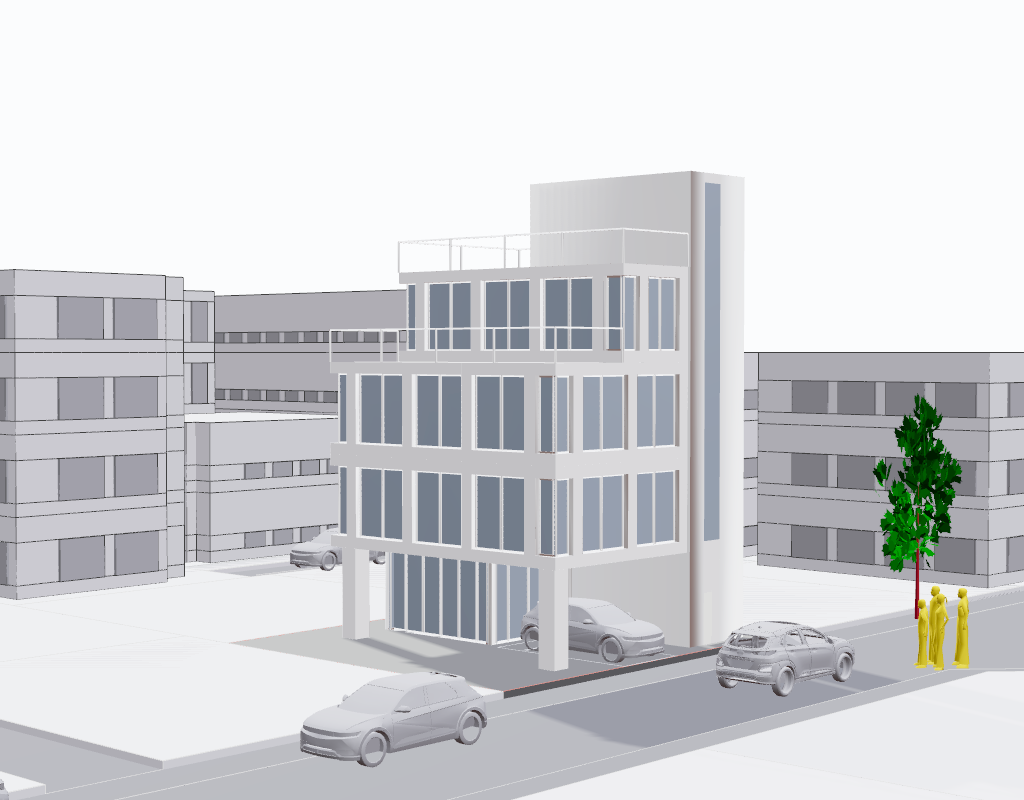
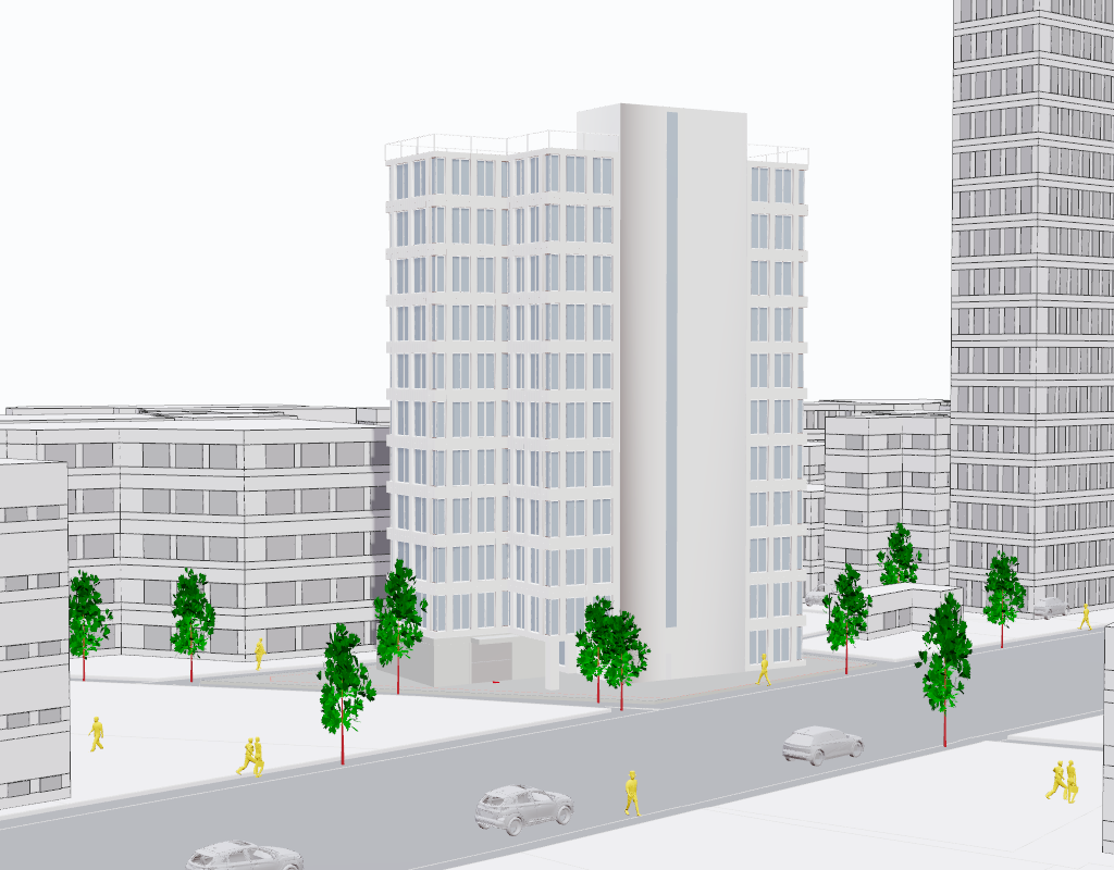
Scale Figures
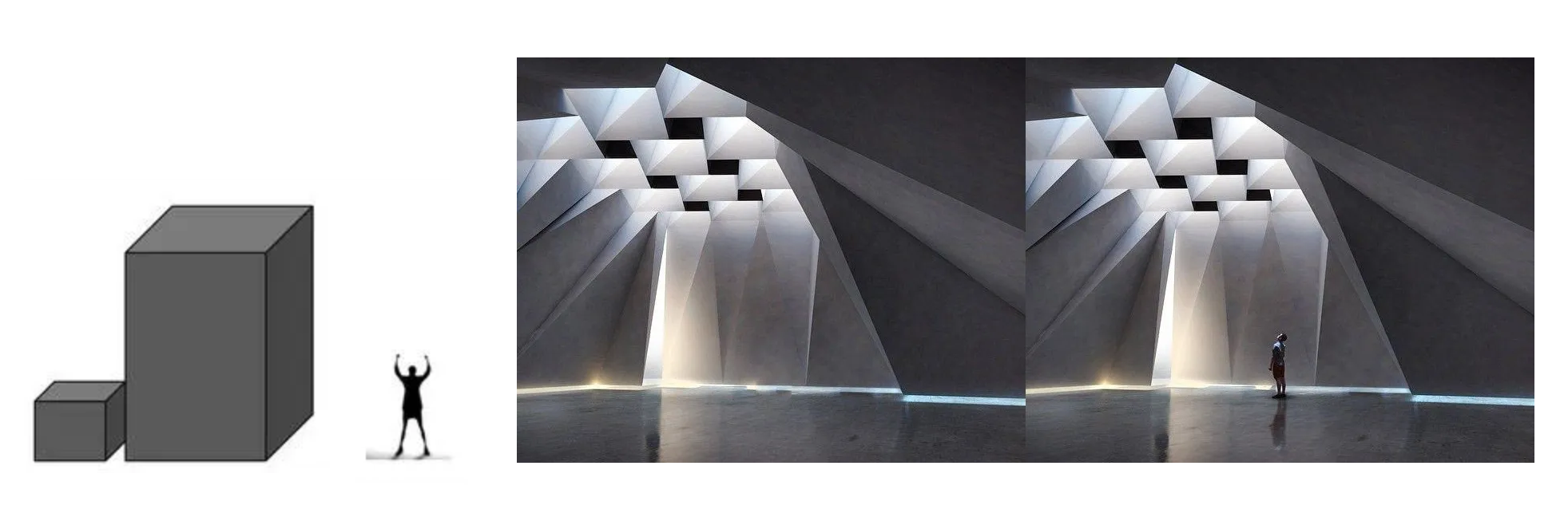
Scale figures serve as essential contextual elements for the diffusion model to understand and generate more realistic architectural visualizations. By incorporating human figures, trees, and vehicles into the scene, we provide the model with crucial reference points that help it comprehend the spatial relationships and scale of the architecture it needs to generate. Scale Figures The presence of these contextual elements also guides the model in generating appropriate lighting, shadows, and atmospheric effects. When the model sees a human figure or a tree in the scene, it can better interpret the scale of lighting effects and environmental interactions that should be present in the final rendering. This helps create more convincing and naturally integrated architectural visualizations.
In our pipeline, these scale elements are placed before the diffusion process begins. The model uses these references to better understand the intended size and proportions of the building, which significantly improves the quality and accuracy of the generated images. Human figures are particularly important as they provide the diffusion model with a scale reference that helps maintain consistent and realistic proportions throughout the generation process. Landbook AI Architect result w/ and w/o scale figures
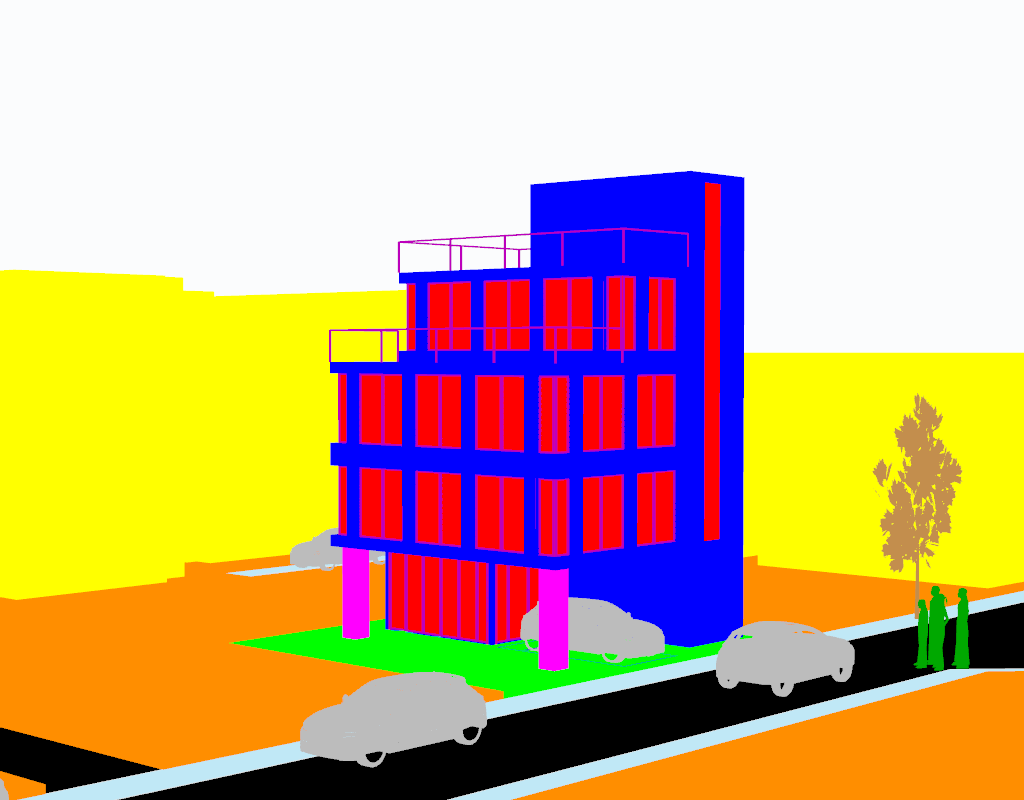
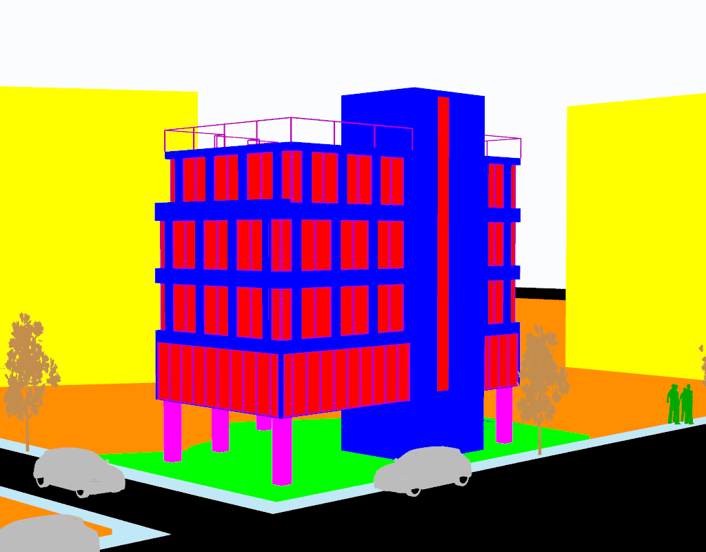
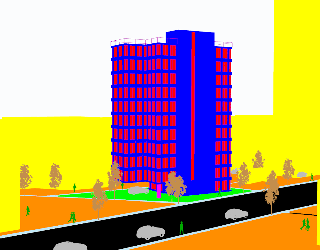
Material Masking
ShaderMaterial provided by three.js is used to mask the materials of the building and the environment. ShaderMaterial is a material rendered with custom shaders. A shader is a small program written in GLSL that runs on the GPU.
Since ShaderMaterial allows users to write custom shaders, we can create specialized masking materials by defining specific colors for different architectural elements. These masking materials help segment the 3D model into distinct parts that can be processed separately by the diffusion model. Material Masking
The diffusion process in our pipeline utilizes multiple specialized models from the HuggingFace Diffusers library to generate photorealistic architectural visualizations. The process consists of three main stages: initial generation, targeted inpainting, and final refinement. The pipeline begins with StableDiffusionXLControlNetPipeline using a ControlNet model trained on canny image. Canny edge detection, highlighting the main building, hatching some parts This stage takes the edge information from our 3D model and generates a base image. The ControlNet helps ensure that the generated base image follows the precise geometric outlines of the building design with the help of the prompt:
    self.prompt_positive_base = ", ".join(
        [
            "<>",
            "[Bold Boundary of given canny Image is A Main Building outline]",
            "[Rich Street Trees]", "[Pedestrians]", "[Pedestrian path with hatch pattern paving stone]",
            "[Driving Cars on the asphalt roads]", "At noon", "[No Clouds at the sky]", "First floor parking lot",
            "glass with simple mullions", "BLENDED DIVERSE ARCHITECTURAL MATERIALS", "Korean city context",  "REALISTIC MATERIAL TEXTURE",
            "PROPER PERSPECTIVE VIEW",  "PROPER ARCHITECTURAL SCALE", "8k uhd", "masterpiece", "[Columns placed at the corner of the main building]"
            "best quality", "ultra detailed", "professional lighting", "Raw photo", "Fujifilm XT3", "high quality",
        ]
    )
After the initial generation, the pipeline performs a series of targeted inpainting operations using StableDiffusionXLInpaintPipeline. The inpainting process follows a specific order to handle different architectural elements. Each inpainting step uses crafted prompts and masks to ensure appropriate material textures and architectural details are generated for each element. After each inpainting step, it is merged with the base image to create a new base image.
Road surfaces with asphalt texturing
Surrounding parcels and pedestrian paths
Background elements including sky
Surrounding buildings with appropriate architectural details
( ... ) Masked images
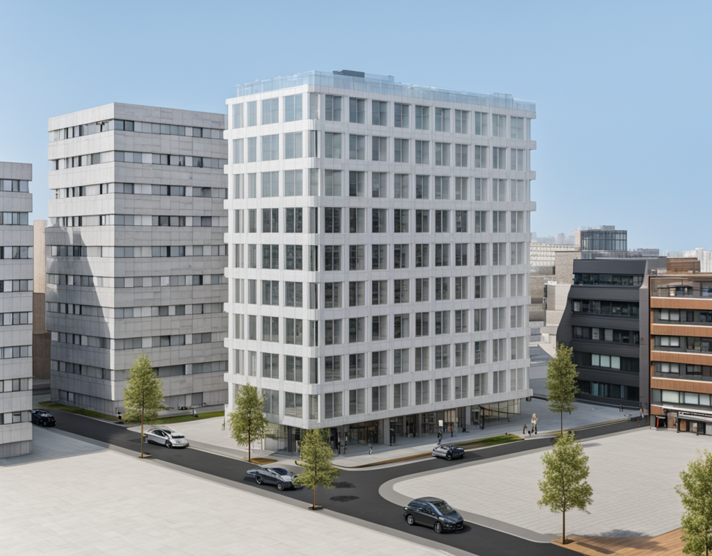
The last stage uses StableDiffusionXLImg2ImgPipeline to refine the overall image, enhancing the coherence and realism of the rendering image. This refinement process focuses on improving overall image quality through better resolution and detail enhancement.
It adjusts lighting and shadows to create more natural and realistic effects, ensures consistent material appearances across different surfaces of the building, and fine-tunes architectural details to maintain design accuracy. These refinements work together to produce a final image that is both architecturally accurate and visually compelling.
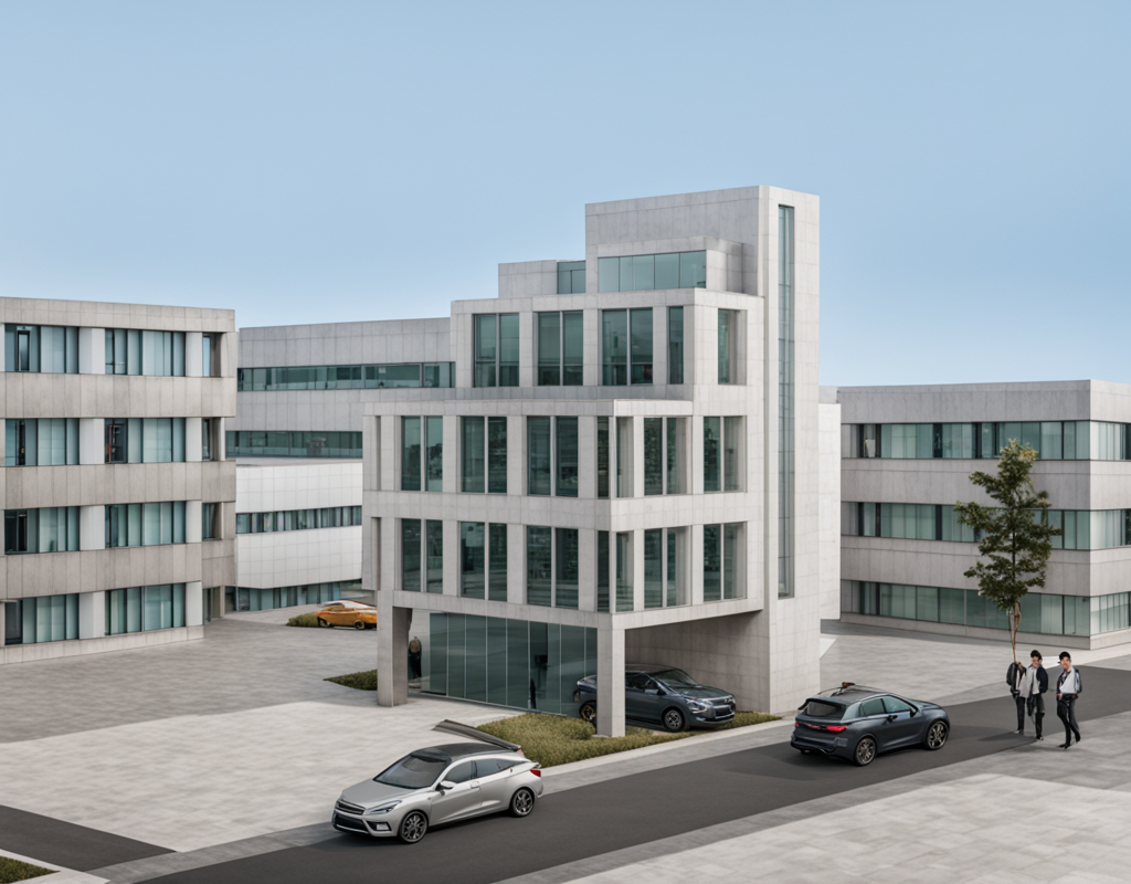
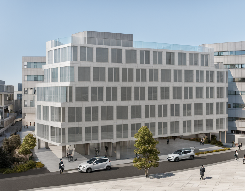
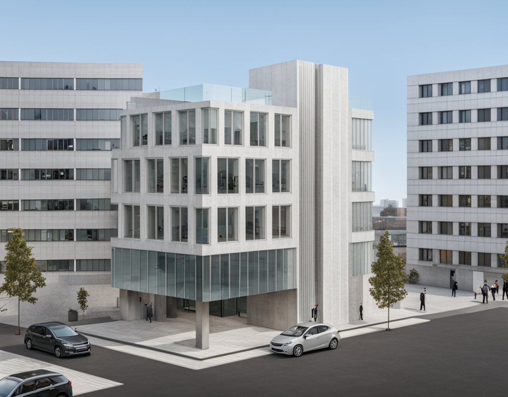
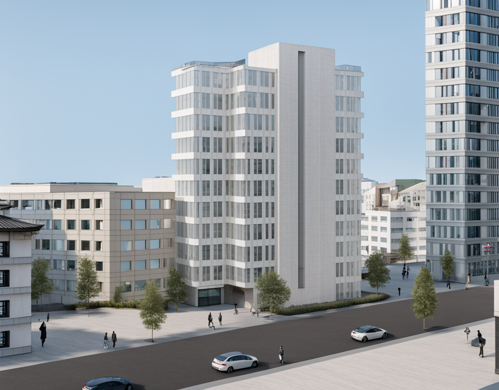
Results
After applying the multi-stage diffusion pipeline described above, we can get the following results which demonstrate the effectiveness of our approach in generating high-quality architectural renderings with consistent materials, lighting, and architectural details.
Future Works
While our current pipeline successfully generates realistic architectural rendering images, there are several areas for potential improvement and future development:
Material Diversity Enhancement: The system could be improved to handle more diverse surrounding building facade textures and materials, along with better material interaction and weathering effects to create more realistic environmental contexts.
Sky Condition Variations: Future development could include support for different times of day, various weather effects and cloud patterns, and dynamic atmospheric conditions to provide more options for visualization scenarios.
Road Detail Improvements: The pipeline could be enhanced to generate more detailed road surfaces, including various pavement types, road markings, surface wear patterns, and better integration with surrounding elements.